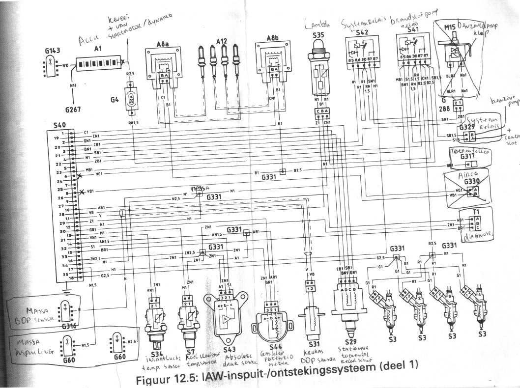
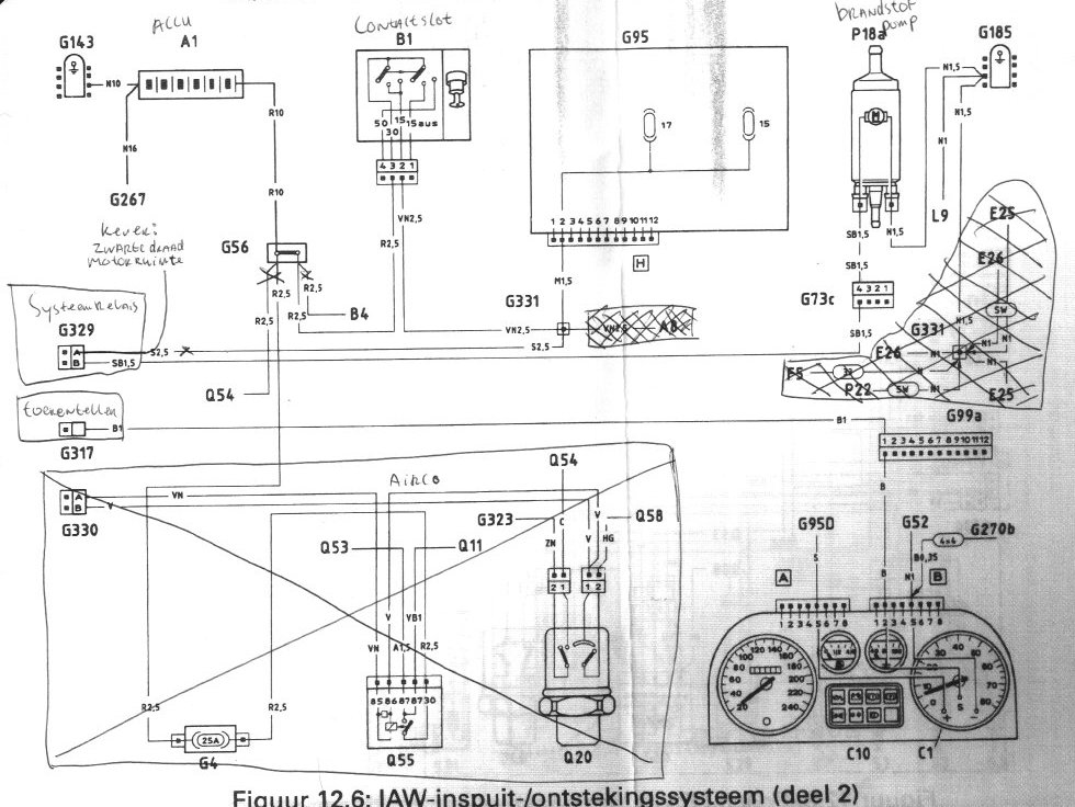
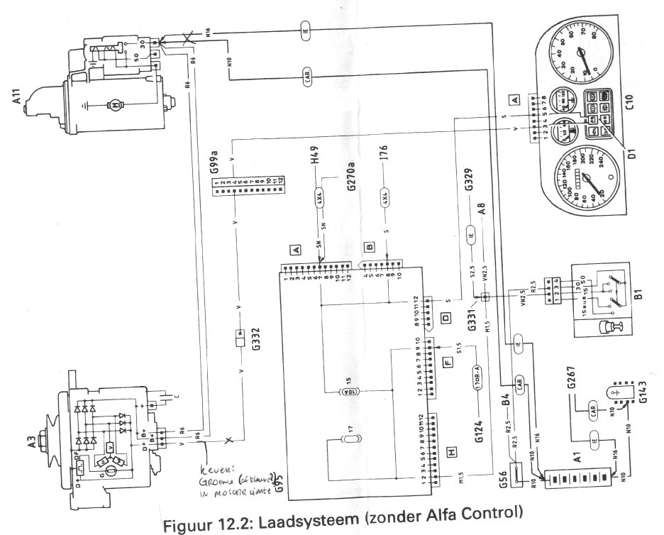
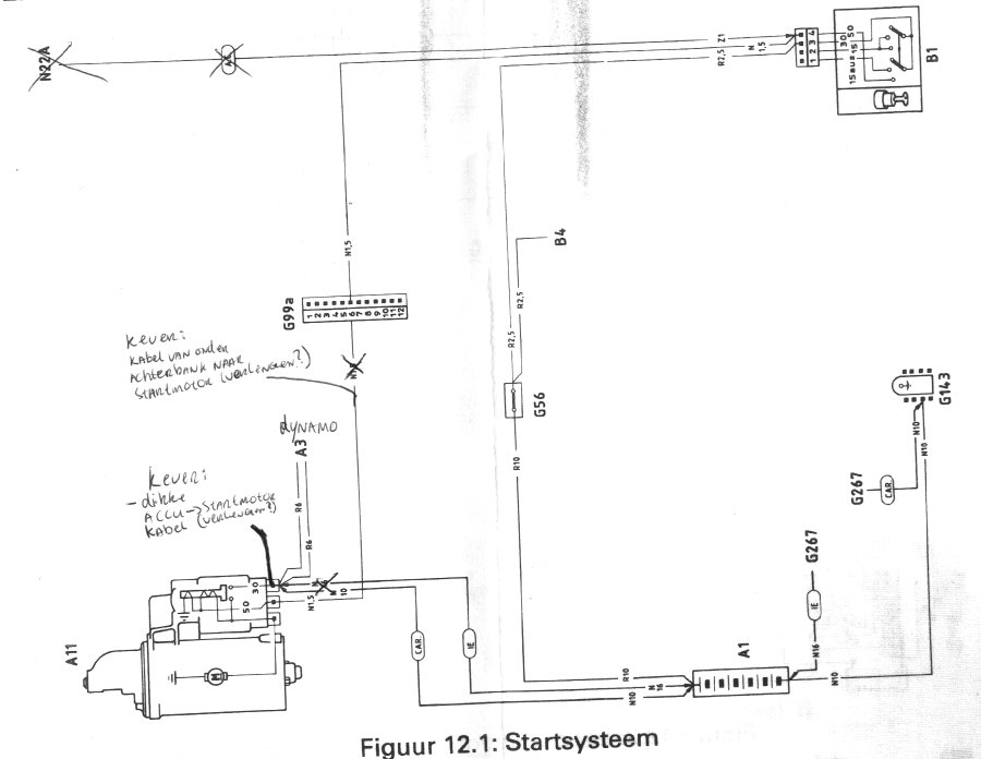
The workshop manual for the Alfa Romeo 33 had the wiring diagrams. They were quite small so I put the book on a xerox machine and enlarged them. Then I put my notes on them (during my holiday in Italy… 🙂 ). My notes are in dutch…just as the titles on the diagrams because it came out of a dutch manual. Almost nobody will have use for these diagrams as they are only for the weber IAW injection system. This system was only used on the 1.4 models.
I’ve put these scans on here for my own administration, but feel free to look at them…
edit 09-04-2006: Before I had some text here about two mistery relays I found on the engine wiring loom. I had more misteries like that… I coulnd’t figure it all out, and I normally I don’t have much difficulty with car-wiring. Then suddenly it dawned on me that I had the wrong engine wiring. The guys at the junkyard put the wiring of a 1.7 engine with bosch injection system on it! That will never work on a 1.4 engine with weber injection! The guys at te junkyard probably cut the wires and after that realised that I said that I wanted the wiring in one piece. So, they took the wiring of another Alfa 33..which was a 1.7….and put it on my 1.4.. Oh well….shit happens. Now I am looking for the engine wiring of a 1.4 Alfa 33..
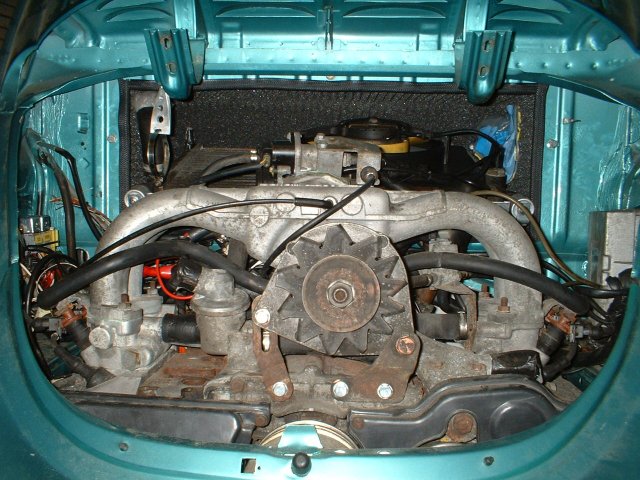
edit 27-05-2006: After being ill for a couple of days I finally had some time again to work on the Alfa beetle. I did some wiring, this is how the engine looks like now:
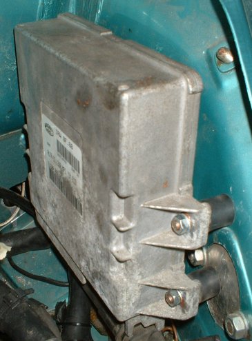
On the right you see the CPU:
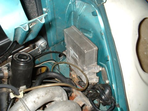
I still have to attach the cpu to the side of the engine bay. I need to get some silent blocks with M6 threads on them for that.
The electric radiator fan is connected:
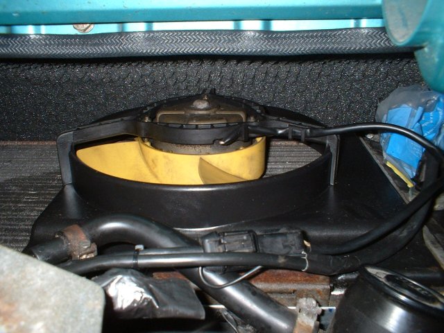
This took some research, because this wiring wasn’t described in the workshop manual…. I connected it so that the thermo switch is connected to the – side of the fan. I first had to test the fan to figure out which wire was + so that it wouldn’t spin the wrong way round (blowing air instead of sucking). The + of the fan is connected to a fuse, and that fuse is getting it’s power directly from the battery. So, if I switch the ignition of, the fan will keep on working… Don’t know if this is good or bad, but I noticed this behaviour on other cars, so it can’t be too bad.
On the left side of the engine bay are the relays and fuses. The last fuse (the one that is labeled “Fan”…) is the fuse for the… fan! The other one is the fuse for the CPU.. Than there is a relay for the fuel pump and one for the CPU. I put the labels on them, I thought that would be handy. I’m sure I’d curse myself if I get stranded somewhere because of a disfunctional fuel pump and I couldn’t remember which relay to replace.
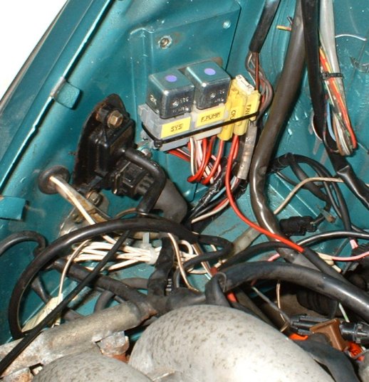
On the left next to the relay is the absolute pressure sensor (=MAP sensor?). I now realise this picture looks a bit like spaghetti…
edit 02-07-2006: I attached the CPU to the right side of the engine-bay. I used silent blocks with M6 threads on either side, this should limit the vibration.
Things that are hooked up:
- oil pressure indicator light
- charging indicator light
- starter engine
- ignition
- all injection sensors
- rev counter
- radiator fan
- oil temp sender
- water temp sender
- engine-overheating sender
- temperature gauge
- engine-overheating indicator light
- fuel pump
- lambda sensor
Waarom heb je voor en achter een radiateur gedaan? Zou het ook alleen voor kunnen dat de achterbank er nog in kan?
Hoi Levi,
Ik had eerst de radiateur achterin, maar dit werkt niet goed. Toen ik heb ik hem daar verwijdert en hem voorin de neus geplaatst.
En dat werkt al jaren zonder problemen. 🙂
Groeten,
Gerrelt.
Complimenten voor je mooie website en vooral de wiring diagrams. Ik heb een Alfasud project, waar een Alfa 33 motor met IAW injectie in is gezet. Er was eea ge-hot-wired, waardoor niet alles goed werkte. Stationair werd niet geregeld, toerenteller signaal was er niet. Doordat je in jouw wiring diagrams erbij hebt gezet waar wat voor is en hoe het is aangesloten ben ik hier enorm mee geholpen en werkt het weer zoals het hoort!
Super! Veel plezier met de Alfa!